Drawing a Cylinder
Transformation Matrices
| Home | |
 |
Back To Tips Page |
|
Drawing a Cylinder
|
|
 This little project arose as part of a discussion in the newsgroup about "How can I draw a cylinder?" As far as I can tell, the poster really needed to use something like OpenGL or Direct3D to draw the image of a cylinder, but it got me thinking about a simpler problem, how to create a cylindrical image, which I might want to use as, for example, a histogram element. Besides, I was trapped on an airplane going to San Diego, and it was either write code or read science fiction, so this seemed a bit more productive.
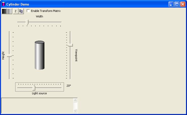
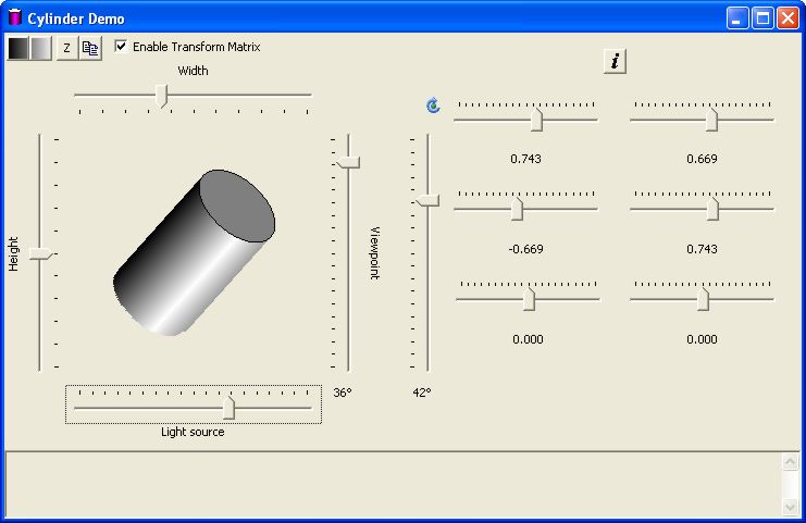
The Cylinder program is shown here. It has some sliders that control the width and height of the cylinder (expressed as a percentage of the total drawing area), the angle of the view, and the angle of the light. There are a couple buttons to specify the color scheme used for the dark and light parts of the drawing.
Other than a table, which takes 25 lines, the actual code that does the cylinder drawing is less than 70 lines of declarations and computations. So the whole thing is under 100 lines of code. The remaining 3,700 lines are simple methods that set/get the parameters to the drawing, and provide all the support, pretty buttons, fancy slider controls, and similar parts of the interaction. About 1300 lines of source code provide the basic interaction. A lot of these deal with the fact that I chose to make the dialog resizable, and the controls float around on it (this is the closest I've come to going to the effort to get a control geometry manager package installed).
 |
 |
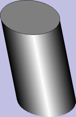
I worked out the basic highlighting technique using my GradientFill Explorer; it takes four points to specify the cylinder fill: from dark to light, and from light to dark.
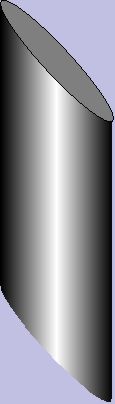
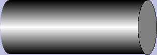
The problem with the simple approach is that it produces a rectangle with a simulated 3-D effect:

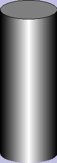
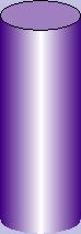
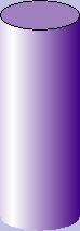
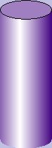
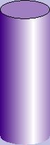
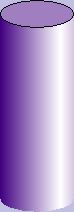
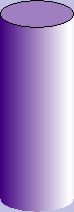
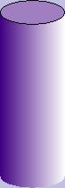
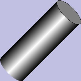
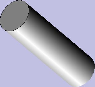
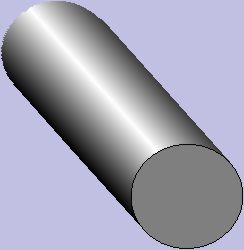
This is not entirely convincing. I really had in mind something more along the lines of a cylinder form
So the question was, how hard would this be to draw using just straight GDI functions, not requiring any 3-D support?
The answer is obviously "yes" because I have demonstrably done it. However, I was on my own to perform all the geometric computations required to make this so. Also, I did not attempt to "rotate" the cylinder itself, or allow anything to be inside it, or try to give a perspective drawing as the viewing angle changed. So I have made a number of simplifying assumptions here that allow me to do a number of simpler drawing techniques than would be required to generally show a 3-D cylinder shape from any angle, or with perspective.
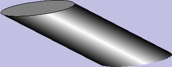
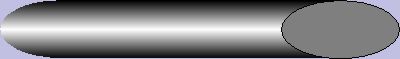
The answer turned out to be: not hard at all. But there are a few tricks I needed to do to make it look just right. For example, I wanted to change the angle of the light from dead-on-straight to allow any angle from -90° to +90°:
 |
 |
 |
|
 |
 |
 |
 |
| -90° | -45° | -15° | 0° | +20° | +40° | +60° | +90° |
This is not entirely obvious how to get the best-looking effect. My first attempt, for example, just did a double-gradient-fill effect with the left and right endpoints forming a 4-strip gradient fill; this is the 0 effect. The problem was that as I changed the angle, the left end (moving to the left) or right end (moving to the right) remained at the same intensity on the edge, which was the dark color. This was not a satisfactory illusion. The illustration below is captured from the GradientFill Explorer.

It you look at this, it does not look like the image is a smooth cylinder; our experience tells us that the dark edge must be the same distance away from our eyes on each side, and therefore it looks like the curve suddenly becomes tighter after the highlighted area.
It turns out that the correct trick was to compute the distance edge-to-peak on the "shadowed" side and then draw an image of the same width, peak-to-new-edige, on the "lighted" side, and clip this to the size of the actual cylinder. Compare the algorithm used by the naive gradient to the "smart" gradient, again, as shown by the Gradient Fill Explorer:
|
Naive gradient fill |
 |
Smart gradient fill: total size |
 |
Smart gradient fill: clipped to original size |
The algorithm was
 |
     CPoint pt(-(width / 2), -(height / 2) );
     double theta = DEGREES_TO_RADIANS((double)lightAngle);
     double xoffset = ((double)width / 2.0) * sin(theta);

     // The distance dx is the distance from the center line to
     // the point of peak brightness.  Note that dx could be negative
     int dx = (int)xoffset;

     // Compute the x-coordinate of the peak of the brightness
     int peak = pt.x + (width / 2) + dx;

     // Assume for the moment that the width we are going to draw
     // is the actual width of the image
     int left = pt.x;
     int right = pt.x + width;

     // Now adjust either the right or the left so that the new
     // point places the peak in the center of the area computed,
     // that is, peak == (right - left) / 2
     // after we adjust left and right

     if(dx < 0)
        left = peak - (right - peak);
     else
        right = peak + (peak - left);
|
 |
     // Compute the size of the end cap. Start by assuming
     // both end caps are "flat", that is, of 0 height
     // These two elements will be used to draw the ellipse
     // for each end

     CRect top   (pt.x, pt.y,          pt.x + width, pt.y);
     CRect bottom(pt.x, pt.y + height, pt.x + width, pt.y + height);

     // Now "rotate" the end cap by the amount based on the eye angle
     double rotate = DEGREES_TO_RADIANS(eyeAngle);

     // Compute the size of the upper curve and the size of the
     // lower curve of the end caps.  Remember that in MM_TEXT
     // mode (the coordinates we are using) the y-axis
     // increases downward
     int dy = (int) (fabs((double)(width / 2) * sin(rotate)));
|
 |
      // Create a region based on the body dimenions
     CRgn rectRgn;
     rectRgn.CreateRectRgnIndirect(&bodyRect);

     // Create a bounding rectangle for the endcap
     CRect curveRect(pt.x, -dy, pt.x + width, dy);

     // Compute the total size of the "fill" rectangle, which is
     // gradient-filled.  If the eye is "above" the center, we
     // will see the top as an ellipse and the bottom as a curve
     // If the eye is "below" the center, we will see the top
     // as a curve and the bottom as an ellipse

     if(eyeAngle > 0)
        { /* has top */
         top.top = pt.y - dy;
         top.bottom = pt.y + dy;
         curveRect.top += pt.y + height;
         curveRect.bottom += pt.y + height;
        } /* has top */
     else
        { /* has bottom */
         bottom.top = pt.y + height - dy;
         bottom.bottom = pt.y + height + dy;
         curveRect.top += pt.y;
         curveRect.bottom += pt.y;
        } /* has bottom */

     // Create a clipping region for the curve.  This will be
     // used to "truncate" the rectangular area we fill to
     // just show the curved part
     CRgn curveRgn;

     // In GDI, the endpoint is up-to-but-not-including the
     // maximum right side.  The problem with this is that
     // the end cap will come out a bit short, so add 1 to
     // compensate for this feature
     if(::GetGraphicsMode(dc) != GM_ADVANCED)
        curveRect.right++; // allow for standard off-by-one issue

     // Now create a region that is an ellipse
     curveRgn.CreateEllipticRgnIndirect(&curveRect);

     // "OR" the region into the current body region to extend
     // it to include the elliptical area.  The parts of
     // the ellipse that overlap the rectangle don't matter;
     // the parts that extend beyond the body region will give
     // us the bottom curve or top curve that we need

     rectRgn.CombineRgn(&rectRgn, &curveRgn, RGN_OR);
|
 |
     TRIVERTEX tv[4] = {
        {   left,  pt.y - dy,
                                       MAKEWORD(0, GetRValue(darkColor)),
                                       MAKEWORD(0, GetGValue(darkColor)),
                                       MAKEWORD(0, GetBValue(darkColor)),
                                       MAKEWORD(0, 255)},
        {   peak,  pt.y + height + dy,
                                       MAKEWORD(0, GetRValue(lightColor)),
                                       MAKEWORD(0, GetGValue(lightColor)),
                                       MAKEWORD(0, GetBValue(lightColor)),
                                       MAKEWORD(0, 255)},
        {   peak,  pt.y - dy,
                                       MAKEWORD(0, GetRValue(lightColor)),
                                       MAKEWORD(0, GetGValue(lightColor)),
                                       MAKEWORD(0, GetBValue(lightColor)),
                                       MAKEWORD(0, 255)},
        {   right, pt.y + height + dy,
                                       MAKEWORD(0, GetRValue(darkColor)),
                                       MAKEWORD(0, GetGValue(darkColor)),
                                       MAKEWORD(0, GetBValue(darkColor)),
                                       MAKEWORD(0, 255)},
     };

     GRADIENT_RECT gr[2] = {
        {0, 1},
        {2, 3},
     };

     // Select the new clipping region and gradient-fill the
     // area.  The clipping region limits the gradient fill
     // so that the extended "spillover" of the left or right
     // will not actually draw

     { /* draw gradient */
      int save2 = dc.SaveDC();

      //******************************************************************
      // This transformation only works for straight GDI without
      // GM_ADVANCED graphics mode being set
      // See the advanced transformation technique for general
      // transformation matrices
      CPoint offset = dc.GetViewportOrg();
      clipRgn.CopyRgn(&rectRgn);
      clipRgn.OffsetRgn(offset);
      //******************************************************************

      dc.SelectClipRgn(&clipRgn);

      BOOL result = dc.GradientFill(tv, 4, gr, 2, GRADIENT_FILL_RECT_H);
      dc.RestoreDC(save2);
     } /* draw gradient */
|
|
|
     // Create a brush which is the "average" color for the end cap
     COLORREF endcap = RGB( (GetRValue(darkColor) + GetRValue(lightColor)) / 2,
                            (GetGValue(darkColor) + GetGValue(lightColor)) / 2,
                            (GetBValue(darkColor) + GetBValue(lightColor)) / 2);
     CBrush ecb(endcap);
     dc.SelectObject(&ecb);

     if(!top.IsRectEmpty())
        dc.Ellipse(&top);
     if(!bottom.IsRectEmpty())
        dc.Ellipse(&bottom);
|
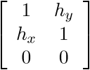
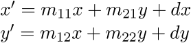
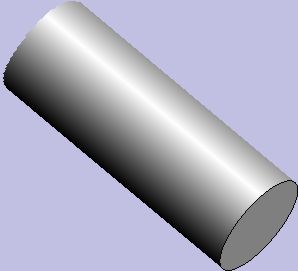
The basic code was quite simple, but I wanted to be able to rotate the cylinder as well. This became a lot more interesting, and a lot more challenging. In GM_ADVANCED mode, you can use a transformation matrix to perform operations such as rotation, offset, and shear. A transformation matrix is formally a 9-element matrix, and matrix operations such as matrix multiply can apply to sequences of matrices. However, the matrix is always represented as
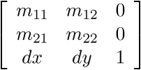
Because the last column is always the constants 0,0,1, the transformation matrix only needs the 6-tuple
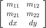
When this matrix is applied to a point (x, y), the computation is
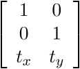
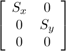
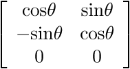
The following are classic parameter values for the matrix
|
|
|
|
|
| Displacement by the values tx ty | Scaling in x,y by scaling factors sx, sy | Rotation counterclockwise by q | Shear by hx. hy |
Clicking the Enable Transformation Matrix check box enables the matrix controls.
| Control | Function |
| Selects the edge and center colors for the cylinder. These two buttons together are gradient-filled with the selected colors. | |
| "Zeroes" the Width, Height, Viewport, and Light Source controls to their startup positions | |
| Copies the cylinder and its background to the clipboard | |
| Enables the use of GM_ADVANCED mode and a transformation matrix. The transformation matrix controls will appear | |
 |
Establishes the width as a percentage of the image area. The range is 0% to 100% |
 |
Establishes the angle of the lighting. The range is in degrees, from -90° to +90° |
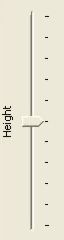 |
Establishes the height as a percentage of the image area. The range is 0% to 100% |
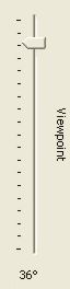 |
Establishes the viewpoint of the eye. The range is -45° to +45° |
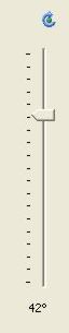 |
Plugs values into the transformation matrix for
a rotational transformation.
Note that using this control will replace the values for M11, M12, M21 and M22. It will leave Dx and Dy unchanged. The angle of rotation is displayed at the bottom. The range of rotation is from -90° to +90°. |
|
|
Replaces the matrix with the identity
transformation,
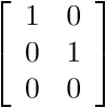 |
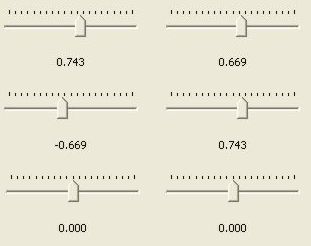 |
These controls are the six control points of
the matrix
|
 |
 |
 |
 |
||||||||||||||||||||||||||||||||||||||||||||||||
|
|
|
|
A transformation matrix is capable of much more, for example, shear operations
|
|
 |
 |
 |
 |
||||||||||||||||||||||||||||||||||||||||||||||||||||||||||||
|
|
|
|
|
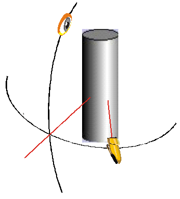
The interesting thing about this experiment was that, while it was clearly more complex than it would take to draw a cylinder using something like OpenGL, it was not impossible, or, once the basic ideas were established, even particularly difficult. The trick was in figuring out the sequence of operations.
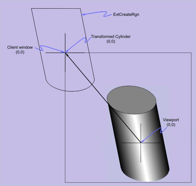
The only trick was the realization that the documentation of CDC::SelectClipRgn was incomplete and misleading. It states that the coordinates are in units of device space, but in fact this is not true. The coordinates of the clipping region is in the coordinate space of the device space. Once that realization was made the trick was to simply create a transformed clipping region. The ExtCreateRegion, which does not have a method of the CDC class, will do this. So all I had to do was
This is shown in the code below. Note that there is no need to do this complex operation if the GM_ADVANCED graphics mode is used, so the "original" code is used.
 |
     // Select the new clipping region and gradient-fill the
     // area.  The clipping region limits the gradient fill
     // so that the extended "spillover" of the left or right
     // will not actually draw

     { /* draw gradient */
      int save2 = dc.SaveDC();

      //*********************************************************************************
      // This code creates a transformed clipping region using the current transformation
      // matrix.  It is a generalization of the "straight GDI" clipping region
      // computation
      if(::GetGraphicsMode(dc) == GM_ADVANCED)
         { /* may need transform */
          XFORM Matrix;
          ::GetWorldTransform(dc, &Matrix);
          //  +-         -+
          //  |  M11  M12 |
          //  |  M21  M22 |
          //  |   dx   dy |
          //  +-         -+
          CPoint originalOffset( (int)Matrix.eDx, (int)Matrix.eDy);

          // To make this work under rotation we have to normalize it
          // to (0,0) so it rotates without displacements
          Matrix.eDx = 0.0f;
          Matrix.eDy = 0.0f;
          //  +-         -+
          //  |  M11  M12 |
          //  |  M21  M22 |
          //  |   0    0  |
          //  +-         -+

          // Now create a new region transformed by the matrix
          CRegionData data;
          data.Set(clipRgn);
          HRGN xformrgn = ::ExtCreateRegion(&Matrix, data.GetSize(), data.GetData());
          clipRgn.DeleteObject();
          clipRgn.Attach(xformrgn);

          // Now slide the region over so it overlaps the area of the cylinder
          CPoint offset = dc.GetViewportOrg();
          clipRgn.OffsetRgn(offset);
          clipRgn.OffsetRgn(originalOffset);
         } /* may need transform */
      else
         { /* non-transform */
          // This is the "straight GDI" code
          CPoint offset = dc.GetViewportOrg();
          clipRgn.CopyRgn(&rectRgn);
          clipRgn.OffsetRgn(offset);
         } /* non-transform */
    //***********************************************************************************
|
The parameters of the Cylinder class are set with the methods of the class. There would be one instance of a Cylinder object for each cylinder to be drawn.
| Cylinder::Cylinder() | Constructor
|
||||||||||||||||
| void Draw(CDC & dc); | Draws the cylinder object on the DC, based on the parameters which have been set. The constructor sets specific defaults. | ||||||||||||||||
| void GetColor(COLORREF & light, COLORREF & dark); | Retrieves the light and dark highlighting
colors of the cylinder See Also: GetDarkColor, GetLightColor, SetColor, SetDarkColor, SetLightColor |
||||||||||||||||
| COLORREF GetDarkColor(); | Retrieves the dark highlighting color of the
cylinder See Also: GetColor, GetLightColor, SetColor, SetDarkColor, SetLightColor |
||||||||||||||||
| int GetEyeAngle(); | Retrieves the vertical viewing angle See Also: SetEyeAngle |
||||||||||||||||
| int GetHeight(); | Retrieves the height of the cylinder, in
logical units. See Also: SetHeight |
||||||||||||||||
| int GetLightingAngle(); | Retrieves the angle of the light shining on the
cylinder See Also: SetLightingAngle |
||||||||||||||||
| COLORREF GetLightColor(); | Retrieves the light highlighting color of the
cylinder. See Also: GetColor, GetDarkColor, SetColor, SetDarkColor, SetLightColor |
||||||||||||||||
| BOOL GetMatrix(XFORM & M); | If there is an active matrix selected, stores
the parameters in the matrix M, and returns TRUE. If the
SetMatrix was for NULL, will not change M and will
return FALSE See Also: SetMatrix |
||||||||||||||||
| CPoint GetPos(); | Retrieves the position of the centroid of the
cylinder in logical coordinates. See Also: SetPos |
||||||||||||||||
| CSize GetSize(); | Retrieves the current width and height of the cylinder in logical units. | ||||||||||||||||
| int GetWidth(); | Retrieves the current width of the cylinder in logical units. | ||||||||||||||||
| void SetColor(COLORREF light, COLORREF dark); | Sets the two colors used for the lighting
effects. If this is not called, a default color
is used. See Also: GetColor, GetDarkColor, GetLightColor, SetDarkColor, SetLightColor |
||||||||||||||||
| void SetDarkColor(COLORREF c); | Sets the dark color used for the lighting
effects. If this is not called, a default color
is used. See Also: GetColor, GetDarkColor, GetLightColor, SetColor, SetLightColor |
||||||||||||||||
| void SetEyeAngle(int degrees); | Sets the viewing angle, in degrees. If
this is not called, a default value is used. The viewing angle is limited to the range -45° to +45°. See Also: GetEyeAngle |
||||||||||||||||
| void SetHeight(int height); | Sets the cylinder height in logical units. If this is not called, a default value is used. | ||||||||||||||||
| void SetLightingAngle(int degrees); | Sets the lighting angle, in degrees. If this is
not called, a default value is used. The lighting angle is limited to the range -90° to +90°. See Also: GetLightingAngle |
||||||||||||||||
| void SetLightColor(COLORREF c); | Sets the light color for the highlighting. If this is not called, a default color
is used. See Also: GetColor, GetDarkColor, GetLightColor, SetColor, SetDarkColor |
||||||||||||||||
| void SetMatrix(XFORM * M); | Sets the transformation matrix to be used for
drawing the cylinder. If the value is NULL, the cylinder can
only be drawn vertically using the base GDI functionality. See Also: GetMatrix |
||||||||||||||||
| void SetPos(CPoint pt); void SetPos(int x, int y); |
Sets the centroid position for the cylinder.
If this is not called, a default value is
used. See Also: GetPos |
||||||||||||||||
| void SetSize(CSize sz); | Sets the width and height of the cylinder. If this is not called, a default value is used. | ||||||||||||||||
| void SetWidth(int width); | Sets the width of the cylinder. If this is not called, a default value is used. |
There are a lot of simplifying assumptions that apply here that reduce the problem to something manageable in straight GDI
Changing any of these assumptions can result in a slightly-more-difficult to nearly-impossible situation.
| Date | Change |
| 30-Mar-08 | Hans-J. Ude's suggestion for flicker-free code reduction was added. I was just feeling lazy, so I thank him for his contribution. |
| Special thanks also to "Nivel" who converted the .wmf files to .png files for wider browser compatibility. |
![]()
The views expressed in these essays are those of the author, and in no way represent, nor are they endorsed by, Microsoft.